
Glass fence planning has two distinct geometry tasks. A straight-run layout fits supplied panel widths into a known run while keeping regular gaps within the entered range and locating known spigot centers. A raked panel calculation describes one angled panel by converting its length and height measurement bases into horizontal span, vertical end height, blank dimensions, and area. The two tools use different inputs and should be reviewed separately.
Start with supplier-confirmed panel sizes, hardware set-ins, allowable gaps, gate clearances, and the angle or measurement bases for any raked panel. The calculators return geometric specifications from those inputs. They do not select glass, approve field cutting, determine hardware capacity, or establish pool-barrier, structural, or code compliance.
Separate the two glass layout tasks
Use the Glass Fence Panel Layout Calculator for one straight run. It supports supplied equal sizes, adjacent supplied sizes, a known panel sequence, or equal custom dimensions. It can include selected end gaps, one internal gate with entered hinge and latch clearances, an optional fixed hinge panel, and spigot marks from a known set-in and maximum center distance.
Use the Raked Glass Panel Dimensions Calculator for one known angled panel. Choose whether the entered panel length is along the sloping top or horizontal, and whether the entered height is perpendicular to that top or vertical at the ends. Enter any horizontal bottom offset only when it is part of the known geometry. Do not use the raked tool to arrange a multi-panel run.
Fit supplied panels to a straight run
Enter the run in inches or feet, then choose a panel mode and list supplied widths in inches. In a standard mode, the solver searches only the widths you provide: one standard size or two adjacent standard sizes. It does not search every possible combination. Use known sequence when the actual order is already decided, or custom mode when equal dimensions are the intended specification.
For a fixed panel list with no end gaps or gate, regular gap count is panel count − 1. The gap is:
gap = (run − sum of panel widths) ÷ regular gap count
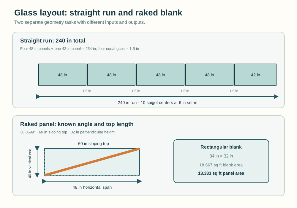
The example run is 240 in with four 48 in panels and one 42 in panel. Panel width total is 4 × 48 + 42 = 234 in. There are four regular gaps, so the remaining width is 240 − 234 = 6 in, and each gap is 6 ÷ 4 = 1.5 in. That lies between the entered 1 in minimum and 2 in maximum.
| Panel | Width | Start | End | Known spigots |
|---|---|---|---|---|
| 1 | 48 in | 0 in | 48 in | 6, 42 in |
| 2 | 48 in | 49.5 in | 97.5 in | 55.5, 91.5 in |
| 3 | 48 in | 99 in | 147 in | 105, 141 in |
| 4 | 48 in | 148.5 in | 196.5 in | 154.5, 190.5 in |
| 5 | 42 in | 198 in | 240 in | 204, 234 in |
The displayed start of panel 2 is 48 + 1.5 = 49.5 in; the same gap repeats between panels. The final panel ends at 240 in. This is a coordinate layout under the entered run origin, sizes, and gap policy. It does not add connector insertion depth, edgework, or a field tolerance unless those are represented by the entered dimensions.
Mark spigot centers
For a panel width P, spigot set-in s from each panel end, and maximum center distance M, the available support span is P − 2s. The calculator uses ceil((P − 2s) ÷ M) support intervals and places the centers at the entered set-in and equal intervals across that span.
For each 48 in panel with 6 in set-in and 36 in maximum centers, available span is 48 − 12 = 36 in. The interval count is ceil(36 ÷ 36) = 1, so the centers are 6 and 42 in. For the 42 in final panel, available span is 42 − 12 = 30 in; its two centers are 6 and 36 in within the panel, which become 204 and 234 in on the run coordinate.
The straight-run example therefore has five panels and 5 × 2 = 10 spigot centers. The calculator also rejects panels too short for the entered set-in and limits total support-coordinate allocation. Support marks are geometric output; they do not select spigot hardware, glass thickness, edge distance approval, or load capacity.
Convert a raked panel
The raked calculator works from an angle between 0° and 45°. With angle θ, sloping-top length T, and perpendicular height H:
- Horizontal length = T cos θ
- Vertical end height = H ÷ cos θ
- Aligned blank length = T + H tan θ when bottom offset is zero
- Panel area = T × H before any bottom-offset adjustment
For a 36.8699° angle, cos θ = 0.8 and tan θ = 0.75. With a 60 in sloping top and 32 in perpendicular height, horizontal length is 60 × 0.8 = 48 in; vertical end height is 32 ÷ 0.8 = 40 in; and the aligned blank length is 60 + 32 × 0.75 = 84 in. The blank height remains 32 in because its axes align to the sloping top and perpendicular height. Blank area is 84 × 32 ÷ 144 = 18.667 sq ft; panel area is 60 × 32 ÷ 144 = 13.333 sq ft.
When a horizontal bottom offset o is entered, the tool adjusts the left end, blank length, and panel area under its declared geometry. It rejects an offset that consumes the available left end or span. Treat the rectangular blank as a fabrication envelope for review. It is not a finished glass cut pattern and does not include edgework, holes, notches, kerf, tolerances, or supplier approval.
Recalculate both examples
| Task | Inputs | Calculation | Result |
|---|---|---|---|
| Straight run | 240 in; 48, 48, 48, 48, 42 in panels; 1–2 in gap | (240 − 234) ÷ 4 | 5 panels; 1.5 in gaps |
| Spigots | 48 in panels; 6 in set-in; 36 in max centers | ceil((48 − 12) ÷ 36) = 1 interval per panel | 2 centers per 48 in panel |
| Raked panel | 36.8699°; 60 in top; 32 in perpendicular height | 60 × 0.8; 32 ÷ 0.8; 60 + 32 × 0.75 | 48 in horizontal; 40 in vertical; 84 in blank length |
| Raked areas | 60 × 32 in panel; 84 × 32 in blank | Divide each square-inch area by 144 | 13.333 sq ft panel; 18.667 sq ft blank |
Check search and geometry limits
The straight-run tool searches only the supplied panel sizes and its supported modes. It allows one internal gate under the entered gate dimensions and selected hinge side, but it does not handle arbitrary multiple gates, end gates, corners, curved runs, or three-or-more-size standard searches. A known sequence can describe a specified arrangement, but it does not verify that a supplier stocks or permits it.
Both tools require positive dimensions and finite inputs. The straight-run layout rejects gaps outside the entered bounds, consumed width, panels too short for support set-ins, more than 100 panels, or more than 1,000 support coordinates. The raked tool accepts 0° as a flat limit and 45° as its inclusive upper limit, and rejects invalid measurement bases, nonphysical offsets, and dimensions that exceed its numeric range.
Do not read a panel coordinate as a finished installation plan. Glass type, thickness, edge treatment, drilling, spigots, brackets, hinges, loads, pool barriers, structural supports, permits, code requirements, field tolerances, and fabrication permissions remain outside these geometric calculators. Confirm the full specification with the supplier or fabricator before ordering or processing glass.
Send a checked specification forward
For a straight run, confirm the origin, supplied panel widths, gap range, end conditions, gate clearances, set-ins, and support coordinates. For a raked panel, confirm the angle and whether each entered length and height is top-based, horizontal, perpendicular, or vertical. Carry the resulting dimensions to the supplier for review rather than treating them as permission to cut or install glass.