
A chain-link fence takeoff becomes difficult when a gate breaks one continuous line into separate stretches. The Chain-Link Fence Material Calculator treats each stretch as a terminal-post-center span, counts gate posts separately, and keeps fabric, top rail, wire, fittings, gate hardware, package sizes, and concrete on their own schedules. That separation makes the result auditable, but it also means the calculator needs an established layout and product plan before you enter numbers.
Use the fence measurement and layout guide first when the post marks or clear openings are still unknown. This guide starts after the project has known straight, level stretches and known gate rows. Its quantities are preliminary takeoff results under the dimensions and recipes you enter; they do not select post sizes, footing dimensions, product compatibility, or a code-compliant installation.
Prepare the known layout
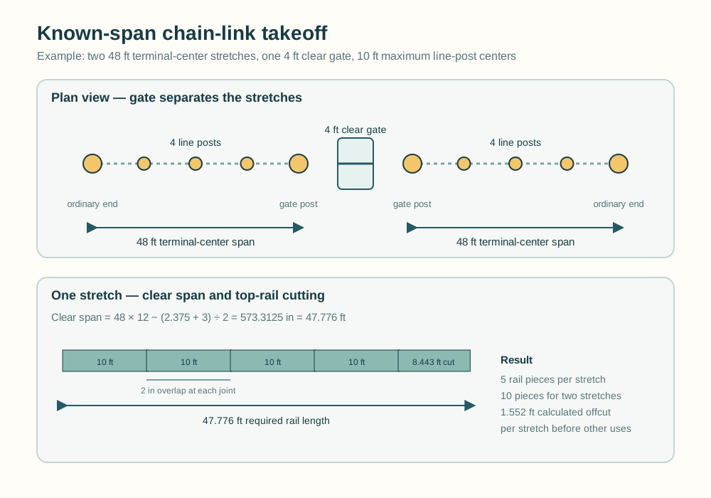
Record each fence stretch from one terminal-post center to the next terminal-post center. A stretch ends at an ordinary end post or at a gate post. Enter the stretches in order, then enter one gate row between every adjacent pair. A gate row contains the gate type, clear opening, hinge-pair count, latch-kit count, and drop-rod count. The calculator accepts one to 20 positive stretches, so a line with one gate has two stretches and one gate row.
Use actual post diameters along the fence line. The profile separately accepts line-post, ordinary-end-post, and gate-post diameters because those dimensions affect the clear span. Enter the fabric height, maximum line-post centers, roll length, rail stock length, joint overlap, end insertion allowance, kerf, wire schedules, pack sizes, and a footing row for every post role that has a nonzero count.
The footing schedule is a known geometry input. Each row identifies a role, hole diameter, hole depth, effective displaced-post diameter, and embedded displacement depth. “Effective displacement” is a calculation input; it is not automatically inferred from a hollow tube’s nominal or outside diameter. The calculator subtracts the entered displaced cylinder from the entered hole cylinder. The layout and footing dimensions must therefore come from the established plan, selected product, site decision, or other project information.
Count stretches, posts, and gate roles
For each terminal-center span s and entered maximum center distance c, the interval count is ceil(s ÷ c). The number of line posts inside that stretch is the interval count minus one. The calculator counts two ordinary end posts for the whole multi-stretch line and two gate posts for each gate row. Every stretch still has two terminal roles, so the total terminal-post count is twice the number of stretches.
For the example, each 48 ft stretch at a 10 ft maximum center distance gives ceil(48 ÷ 10) = 5 intervals and 5 − 1 = 4 line posts. Two stretches therefore contain eight line posts. One gate adds two gate posts, and the two outer ends add two ordinary end posts. The total is 8 + 2 + 2 = 12 posts. The gate posts are not also counted as ordinary ends.
| Role | Input or formula | Result | Meaning |
|---|---|---|---|
| Stretch 1 line posts | ceil(48 ÷ 10) − 1 | 4 | Interior line posts only |
| Stretch 2 line posts | ceil(48 ÷ 10) − 1 | 4 | Interior line posts only |
| Ordinary end posts | Two outer ends | 2 | Not gate posts |
| Gate posts | 2 × one gate row | 2 | One post on each side of the opening |
| Total | 8 + 2 + 2 | 12 | All post roles in this straight layout |
Within each stretch, line-post centers are equally spaced after the interval count is set. The example’s actual center distance is 48 ÷ 5 = 9.6 ft, below the entered 10 ft maximum. This is a distribution calculation. It does not decide whether the selected fence system, height, soil, wind exposure, property conditions, or local requirements allow that spacing.
Convert clear spans into fabric
The calculator first removes half of each terminal post diameter from a terminal-center span. For a stretch with length s, start-post diameter d₁, and end-post diameter d₂, the clear span is:
clear span = s × 12 − (d₁ + d₂) ÷ 2
All terms are in inches in that equation. It then subtracts the entered fabric-end deduction at both ends. With zero deduction, the fabric length equals the clear span. With a positive deduction, the fabric quantity is lower by 2 × deduction for each stretch.
For one example stretch, the span is 48 ft, the ordinary end diameter is 2.375 in, and the gate-post diameter is 3 in. The clear length is 48 × 12 − (2.375 + 3) ÷ 2 = 576 − 2.6875 = 573.3125 in, or 47.7760417 ft. The two identical stretches require 2 × 47.7760417 = 95.5520833 ft of net fabric at zero end deduction.
At a 50 ft roll length and zero allowance, pooled roll purchasing is ceil(95.5520833 ÷ 50) = 2 rolls. Per-stretch rounding also returns two rolls here because each 47.776 ft stretch needs one roll. Those policies can differ when several stretches have different lengths: pooled mode rounds the total compatible fabric, while per-stretch mode rounds each stretch separately. Neither policy authorizes splicing or confirms that a particular fabric product can be joined or reused in the required way.
Plan top-rail pieces and cuts
Top rail is optional. When it is on, the calculator builds a rail requirement for each stretch from the clear span plus the entered end-insertion allowance. It uses the entered stock length, joint overlap, and cut kerf to find a feasible pattern for that stretch. Each stretch receives its own pattern; the result does not globally optimize offcuts across separate stretches.
For the example, the clear span is 573.3125 in, the stock length is 120 in, and the joint overlap is 2 in. With no end insertion, five pieces are sufficient because each joint reduces the next piece’s required advance by 2 in:
ceil((573.3125 − 2) ÷ (120 − 2)) = ceil(571.3125 ÷ 118) = 5 pieces
The first four pieces are 120 in. The final cut is 573.3125 − 4 × 118 = 101.3125 in, or 8.4427083 ft. The calculator reports the rail cut mode and the calculated offcut. Across two stretches, the example uses 10 rail pieces and two identical cut tails.
| Item | Substitution | Result |
|---|---|---|
| Clear rail span | 48 × 12 − (2.375 + 3) ÷ 2 | 573.3125 in / 47.776 ft |
| Stock and overlap | 120 in stock; 2 in overlap | 118 in net advance per added piece |
| Piece count | ceil((573.3125 − 2) ÷ 118) | 5 pieces |
| Final cut | 573.3125 − 4 × 118 | 101.3125 in / 8.443 ft |
| Two stretches | 5 × 2 | 10 pieces total |
Kerf matters when a nominal final tail is almost a full stock piece. If the tail cannot leave enough stock for the entered cut kerf, the calculator switches to an equal-cut pattern that keeps the cuts feasible under its arithmetic model. Treat that output as a cutting estimate. Confirm product-specific rail joints, insertion, coupling, permitted cuts, and field assembly with the selected system before cutting material.
Count wire, ties, fittings, and packs
Wire lines, tie spacing, rail tie spacing, tension bands, brace bands, tensioners, hinge hardware, latch kits, drop rods, and component packs are separate inputs. A zero wire-line count omits wire rolls and wire ties. Turning top rail off omits rail pieces, rail ends, loop caps, rail ties, and rail couplers. Inactive controls are not needed for the calculation.
For the example’s one wire line, 6 in wire-end allowance at both terminations gives 573.3125 + 12 = 585.3125 in per stretch. Two stretches need 2 × 585.3125 ÷ 12 = 97.5520833 ft, so one 100 ft wire roll is enough under the entered roll rule. The line-post tie count is 8 × (ceil(48 ÷ 24) + 1) = 8 × 3 = 24. Rail ties are 2 × (ceil(573.3125 ÷ 24) + 1) = 2 × 25 = 50; wire ties use the same 50-position result. Total ties are 24 + 50 + 50 = 124.
With four terminal posts, one wire line, and one brace band per wire termination, the example has four wire terminations and eight brace bands. Two hinge pairs produce two male hinges, two female hinges, and four hinge bolts. The one single-gate row contributes one latch kit and one single-gate kit. If a component is sold in 100-unit packs, the calculator rounds that component’s purchase independently. For 124 ties, ceil(124 ÷ 100) = 2 packs, or 200 ties purchased with 76 units remaining. A pack size must be a positive whole number and applies only to its named component.
| Schedule | Required | Purchase rule | Example purchase |
|---|---|---|---|
| Fabric | 95.552 ft | 50 ft rolls, pooled | 2 rolls |
| Top rail | 5 pieces per stretch | 10 ft stock with 2 in overlap | 10 pieces |
| Wire | 97.552 ft | 100 ft roll | 1 roll |
| Ties | 124 | 100 per pack | 2 packs / 200 ties |
| Band bolts | 24 | 100 per pack | 1 pack / 100 bolts |
The output is a schedule under the inputs. It is not a product bill of materials unless the selected product’s dimensions, included hardware, pack contents, and installation permissions match those inputs. Do not enter a gate kit’s included hardware again as separate additional hardware.
Estimate concrete from known footing geometry
Concrete is calculated by role rather than by a single average hole. For each role, the geometric volume is:
concrete per hole = π × [(hole diameter ÷ 2)² × hole depth − (effective displacement diameter ÷ 2)² × embedded displacement depth]
Diameters and depths must be converted to feet before multiplying the cylinder volumes. The calculator then multiplies the per-hole volume by the number of posts in that role. The displayed “effective displacement” is the value you supplied for the portion that occupies the hole; it does not claim that every post is a solid cylinder.
For the line-post row, the entered hole is 10 in diameter and 24 in deep, and the effective displacement is 1.625 in diameter over 24 in. In feet, the calculation is:
π × [(5 ÷ 12)² × 2 − (1.625 ÷ 24)² × 2] = 1.062026 cu ft per line-post hole
Eight line posts therefore use 8 × 1.062026 = 8.496208 cu ft. The 12 in by 30 in ordinary-end row contributes 3.773167 cu ft for two posts, and the 12 in by 30 in gate row with a 3 in displacement contributes 3.681554 cu ft for two posts. The total is 15.950929 cu ft. At 0.6 cu ft per bag, pooled purchasing is ceil(15.950929 ÷ 0.6) = 27 bags.
Per-hole rounding produces a different purchase result: line holes are ceil(1.062026 ÷ 0.6) = 2 bags each, end holes are 4 each, and gate holes are 4 each. That gives 8 × 2 + 2 × 4 + 2 × 4 = 32 bags. The difference is a procurement policy, not a disagreement in geometric volume. The calculator keeps pooled and per-hole rounding separate so the user can choose the rule that matches the purchase plan.
Work through the complete example
Enter these values to reproduce the article’s worked case:
| Input group | Values |
|---|---|
| Layout | Runs: 48 ft, 48 ft; gate: single, 4 ft clear, 2 hinge pairs, 1 latch kit, 0 drop rods |
| Posts and fabric | 4 ft fabric height; 10 ft maximum centers; line/end/gate diameters: 1.625 / 2.375 / 3 in; 50 ft rolls; 0% allowance; 0 in end deduction |
| Top rail | On; 10 ft stock; 2 in overlap; 0 in end insertion; 0.0625 in kerf; 24 in tie spacing |
| Wire | 1 line; 100 ft roll; 6 in end allowance; 24 in tie spacing; 1 brace band and 1 tensioner per termination |
| Footings | Line: 10 in × 24 in, 1.625 in × 24 in displacement; end: 12 in × 30 in, 2.375 in × 30 in; gate: 12 in × 30 in, 3 in × 30 in |
| Purchasing | 0.6 cu ft per bag; pooled concrete rounding; ties and band bolts: 100 per pack |
The independently recalculated primary result is 12 posts; 2 fabric rolls. The supporting quantities are 10 rail pieces, 1 wire roll, 124 ties, 27 pooled concrete bags, 1 single-gate kit, 2 male hinges, 2 female hinges, 4 hinge bolts, and 1 latch kit. The calculator displays decimal lengths and volumes to a limited number of places, so a displayed 47.776 ft is a rounded presentation of the unrounded value used for downstream counts.
Check boundaries and limits
An exact center boundary does not create an extra line post. A 10 ft stretch with a 10 ft maximum center distance has ceil(10 ÷ 10) = 1 interval and zero line posts between its two terminal posts. A stretch just above 10 ft requires two intervals and one line post. This is why the terminal roles and line-post count should be checked separately.
The calculator rejects empty or nonpositive stretches, invalid gate rows, nonpositive active roll or stock dimensions, negative allowances, invalid pack sizes, duplicate pack rows, missing active footing roles, displacement that exceeds the selected post or hole geometry, and rail patterns that cannot leave positive usable stock. It allows up to 20 stretches, 1,000 total posts, and 10,000 rail pieces. The numeric checks also reject a positive footing volume that would underflow into a false zero-bag result.
Keep the scope clear. The calculator does not combine corners or shared terminals, interpret slopes, choose safe post spacing, design gate frames, select footing depth, decide soil or wind requirements, approve pool or property-line conditions, infer bracing, or verify product compatibility. Its “concrete” result is a volume and bag takeoff from the entered geometry, not a footing design. Its rail result is a feasible arithmetic cut pattern under the entered stock and overlap rules, not a manufacturer approval.
Review the purchase list
Before ordering, compare each output with the established fence drawing and the selected product information. Confirm that stretch endpoints, gate openings, actual post diameters, fabric roll lengths, rail joints, wire lines, hardware inclusions, pack sizes, footing dimensions, and bag yield all describe the same project. Reconcile shared posts or additional corners outside this straight-run calculation, then carry the confirmed quantities into your purchase list.