
A fence line can rise or fall while the panels remain level, or the panels can follow the ground. Those choices produce different panel lengths, clearances, and post tops even when the route and post spacing are the same. The Fence on a Slope Calculator compares these geometries from a known straight run or a sequence of measured terrain stations. It also compares the calculated post lengths with stock lengths you enter.
Start with the actual route measurements and a fence method already allowed by the project and selected product. The calculator does not determine property boundaries, structural adequacy, suitable embedment, product permissions, or local requirements. Use the fence measurement and layout guide to establish straight-run endpoints and known post layout inputs before working through slope geometry.
Measure the terrain and define inputs
For a uniform grade, enter the horizontal run in feet and the signed elevation change from start to end in feet. A negative change means the far end is lower; a positive change means it is higher. Horizontal distance is the station difference along the plan, not the longer tape distance measured over the sloping ground.
For changing terrain, use survey mode and enter two to 30 station/elevation pairs. The first station must be zero, later stations must increase, and each segment is modeled as a straight line between its two measured points. Use one elevation datum throughout the run. Survey mode treats each adjacent pair as its own terrain section, so every measured transition is retained as a post location. Unmeasured bumps between stations are not inferred.
Enter the maximum horizontal post-center spacing, actual post width along the fence line, vertical fence height, vertical ground clearance, any known post-top allowance, and known burial depth. Also enter the available post stock lengths. These are project inputs, not recommendations. Optional clear-rail-length and rack-rise limits are applied only when selected; a rack limit applies to racked panels, not stepped panels.
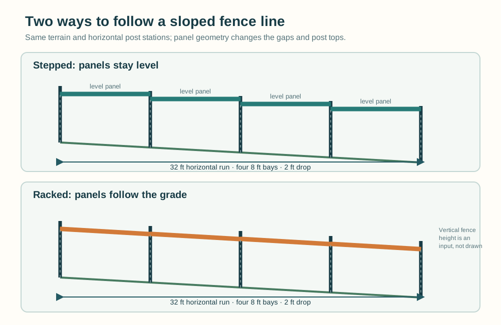
Choose stepped or racked geometry
The calculator divides each measured horizontal terrain section into equal bays. It first uses enough bays to stay within the entered maximum horizontal center spacing. A clear-rail limit, if enabled, can require more bays. The shared transition post between neighboring measured sections is counted once.
In stepped mode, each panel remains level and its bottom is set above the higher ground elevation at the two panel ends by the entered clearance. Because the panel is level while the ground changes beneath it, the gap varies from one end to the other. The calculator reports the end-to-end ground-gap range for each panel. “Stepped” and “racked” are general layout terms; product instructions may define which method, transitions, clearances, and attachments are allowed for a particular fence system.
In racked mode, each panel follows the line between its two terrain endpoints and keeps the entered vertical clearance at both ends. The calculator deducts the actual post width from the horizontal center span to get the clear horizontal rail span, then uses the terrain grade to calculate the diagonal rail geometry. For horizontal center span x, elevation change y, and post width w, the clear horizontal span is x − w. The modeled rail length is (x − w) × √(1 + (y ÷ x)²). This is geometric length only; product connection and insertion allowances are not added.
| Result | Stepped, level panels | Racked, follows grade |
|---|---|---|
| Panel bottom | Level within each bay; set above the higher endpoint by entered clearance | Follows the straight terrain segment at the entered vertical clearance |
| Ground gap | Varies along the panel; reports minimum and maximum | Constant at the entered clearance in the modeled segment |
| Clear rail length | Clear horizontal span after post-width deduction | Diagonal length based on clear horizontal span and grade |
| Rack-rating check | Not applied | Optional entered rise-per-horizontal-foot limit |
Estimate post tops and stock lengths
At a post shared by two panels, the top must clear the higher adjacent panel top in the model. The entered post-top allowance is added above that point. The required post length then adds the known burial depth below the local ground elevation:
required post length = modeled post top − local ground elevation + entered burial depth
For each post, the calculator selects the shortest entered stock size that is at least as long as the required length. It reports unmatched posts when none of the supplied lengths is sufficient. This is a stock comparison, not a cut plan: it does not account for end trimming, defects, connection notches, or reuse of offcuts.
The result depends directly on the entered burial depth and post-top allowance. The tool cannot determine a safe embedment or a required post size from fence height, soil, frost, loads, or local rules. For a separate arithmetic reference based on a fixed multiplier, see the Fence Post Length Calculator; its multiplier is also not a design rule and should not replace project requirements.
Recalculate a uniform-slope example
Consider a 32 ft horizontal run that drops 2 ft, divided at a maximum 8 ft horizontal post-center spacing. Use 4 in actual posts, 6 ft vertical panels, 2 in vertical ground clearance, no post-top allowance, a known 24 in burial, and entered stock lengths of 8, 10, and 12 ft. These values illustrate the arithmetic; they do not recommend fence dimensions or installation conditions.
The number of bays is ceil(32 ÷ 8) = 4, so there are five post locations. The elevation change per bay is −2 ÷ 4 = −0.5 ft, or a 6 in drop. A post is 4 in wide, so each panel has 8 × 12 − 4 = 92 in of clear horizontal span.
For stepped panels, the first bay’s higher ground endpoint is at elevation 0 ft. Its bottom is 2 in above that elevation, or 0.166667 ft; its top is therefore 0.166667 + 6 = 6.166667 ft. At the first post, required length is 6.166667 − 0 + 2 = 8.166667 ft. At the second post, the first panel’s top is higher than the next panel’s top, so the shared post must reach 6.166667 ft. Its local ground is −0.5 ft, giving 6.166667 − (−0.5) + 2 = 8.666667 ft. Each later shared post is calculated from the higher of its adjacent panel tops in the same way.
Under these inputs, the stepped layout requires one 8.166667 ft post and four 8.666667 ft posts. The shortest sufficient entered stock length is 10 ft for all five. For racked panels, each bay follows the grade and holds the same vertical clearance. Its modeled post top follows the local ground, so all five posts require 6 ft + 2 in clearance + 2 ft burial = 8.166667 ft; the same entered stock list selects five 10 ft posts.
| Quantity | Stepped | Racked | Calculation or interpretation |
|---|---|---|---|
| Bays and posts | 4 bays; 5 posts | 4 bays; 5 posts | ceil(32 ft ÷ 8 ft) = 4 intervals; endpoints included |
| Vertical change per bay | −0.5 ft | −0.5 ft | −2 ft ÷ 4 |
| Clear horizontal span | 92 in | 92 in | 8 ft × 12 − 4 in post width |
| Geometric rail per bay | 92 in / 12 = 7.666667 ft | 92 × √(1 + (6 ÷ 96)²) / 12 = 7.681626 ft | Center-span grade is applied to the post-width-adjusted clear span; connection allowances excluded |
| Required post lengths | 1 × 8.166667 ft; 4 × 8.666667 ft | 5 × 8.166667 ft | Panel top minus local ground plus 2 ft known burial |
| Selected entered stock | 5 × 10 ft | 5 × 10 ft | Shortest entered stock at least as long as each requirement |
| Stepped panel end gap | 2.125–7.875 in | 2 in at both ends | Stepped clearance varies with ground; racked keeps entered clearance |
The stepped-post values deserve careful reading: the first post meets a panel whose bottom is above the starting grade, while each following shared post must reach the higher top of its adjacent stepped panels. The 8.166667 ft and 8.666667 ft results follow the stated formula and inputs. The difference between a 7.666667 ft stepped rail and a 7.681626 ft racked rail is small here because the grade is gentle, but they represent different geometries.
Handle a measured hill or valley
A single start-to-end elevation change can hide an intermediate rise or dip. For measured stations (0 ft, 0 ft), (8 ft, 2 ft), and (16 ft, 0 ft), the calculator creates two terrain sections that meet at the 8 ft station. With 8 ft maximum centers, zero clearance, a 6 ft panel height, 2 ft known burial, 4 in posts, and stock lengths of 8, 10, and 12 ft, the center post is shared by both sections.
Each endpoint post requires 6 ft fence height + 2 ft burial + 2 ft terrain elevation relative to its panel base = 10 ft. The center post sits at the hill crest and requires 8 ft under the entered geometry. Thus the three required lengths are 10, 8, and 10 ft; stock selection returns two 10 ft posts and one 8 ft post. A uniform 16 ft rise-to-fall assumption would miss the measured center transition, so retain survey points when the terrain changes direction.
Station/elevation interpolation assumes a straight ground segment between each pair of points. Add stations where the measured profile changes; the calculator does not reconstruct terrain between sparse observations or create corners, branches, and gates.
Apply rail and rack limits
The spacing input limits horizontal center distance, not sloped surface distance. In the uniform example, the ground distance for one 8 ft bay with a 0.5 ft elevation change is √(8² + 0.5²) = 8.0156 ft. The tool still checks the entered 8 ft horizontal center limit, then reports ground-line distance separately.
An optional maximum clear-rail length can force additional bays if a panel’s calculated clear rail exceeds the entered value. A rack limit is expressed as allowed elevation rise in inches per horizontal foot and is checked against each racked terrain section. Enter only a limit already established for the selected product or project. A passing check means only that the geometry is within the number supplied; it does not validate a product, connector, load, or installation.
For a flat 8 ft run with one 6 ft panel, zero clearance, and a known 2 ft burial, the two posts each require exactly 6 + 2 = 8 ft. An 8 ft entered stock length is an exact fit. If the available list were only 6 ft, the calculator would flag both posts as unmatched rather than inventing a longer size.
Check assumptions and exclusions
Uniform mode requires a positive run and finite signed elevation change. Survey mode requires two to 30 points, a zero start station, and strictly increasing horizontal stations. Maximum spacing and fence height must be positive; post width, clearances, allowances, and burial depth cannot be negative. The calculator rejects a panel opening consumed by post width, invalid or excessive layouts, and a racked section that exceeds an enabled rack limit. An enabled rail constraint requires a positive maximum clear length.
Results round displayed dimensions to three decimal places, but calculations use the underlying unrounded values. A displayed post requirement of 8.667 ft is a rounded value; the stock comparison uses the calculated requirement before display rounding. Do not use rounded table values to repeatedly mark later posts, because that can accumulate small differences.
The model handles up to 30 terrain points and 500 panels. It does not include gate openings, corners, branches, curved routes, terrain between survey stations, product-specific bracket or insertion allowances, post cutting, stock reuse, or prices. It does not choose fence height, post spacing, rail size, rackability, burial depth, soil assumptions, footing design, pool barriers, permits, or code compliance.
Carry the layout into the plan
Use measured horizontal stations and consistent elevations, select the stepped or racked geometry already permitted for the project, and compare the calculated openings and post lengths against known product and site requirements. Treat the output as a geometric takeoff under explicit inputs. Confirm structural, footing, connection, cutting, and local requirements independently before ordering or setting posts.